Design and analysis of shell and tube heat exchanger
Designing and analyzing a shell and tube heat exchanger is a complex task that involves understanding both the theoretical and practical aspects of heat transfer, fluid dynamics, and material science. This type of heat exchanger is one of the most common and versatile in industrial applications, thanks to its robust design and ability to handle high pressures and temperatures. Let’s dive into the details.
Introduction to Shell and Tube Heat Exchangers
Shell and tube heat exchangers consist of a series of tubes, one set carrying the hot fluid and the other carrying the cold fluid. The heat exchange occurs between these fluids through the tube walls. This design is popular due to its ability to handle a wide range of temperatures and pressures, as well as its adaptability to different types of fluids.
Components of a Shell and Tube Heat Exchanger
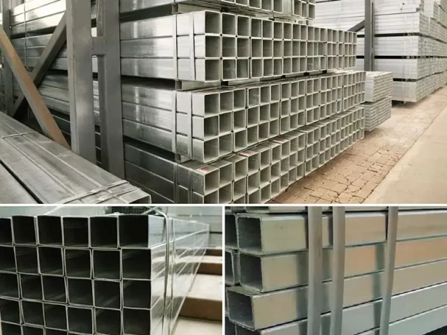
- Shell: The outer casing that holds the tube bundle. It is typically cylindrical and made of metal to withstand high pressures.
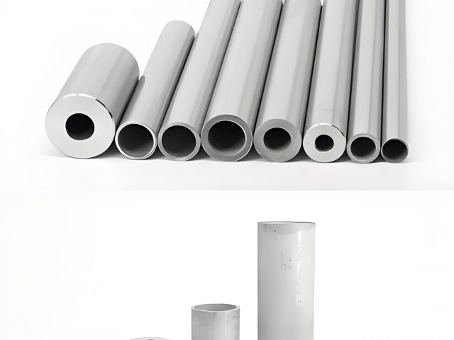
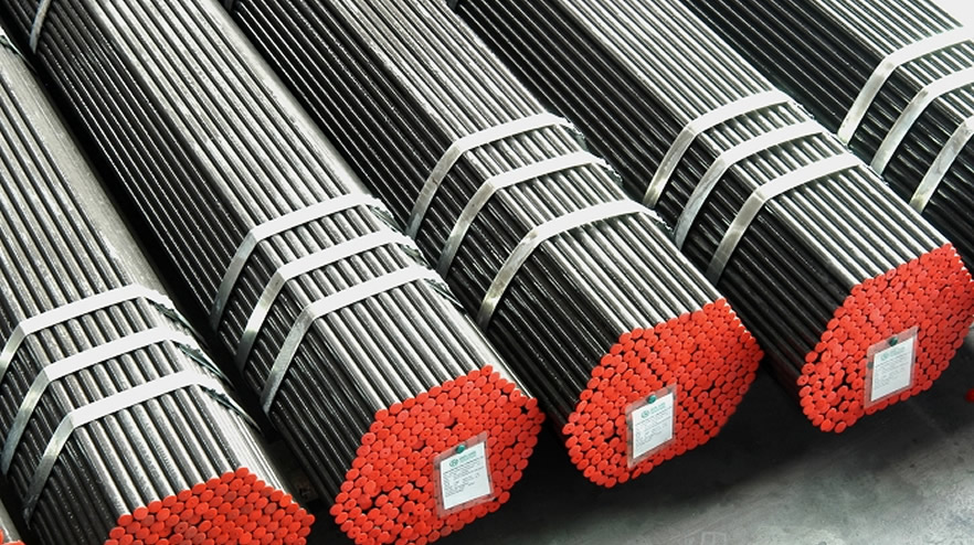
- Tubes: These are the pathways for the fluids. They can be made from various materials, including stainless steel, copper, or titanium, depending on the application.
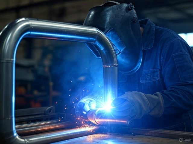
- Tube Sheets: These are plates that hold the tubes in place. They are drilled with holes to accommodate the tubes and are welded or expanded to ensure a tight fit.
- Baffles: These are used to direct the flow of fluid within the shell, increasing the turbulence and improving heat transfer efficiency.
- End Caps or Heads: These are used to close off the ends of the shell and direct the flow of fluid into and out of the tubes.
- Nozzles: These are the entry and exit points for the fluids.
Design Considerations
1. Thermal Design
The primary goal of the thermal design is to ensure efficient heat transfer between the fluids. This involves calculating the heat transfer area required, the number of tubes, and the arrangement of these tubes within the shell.
- Heat Transfer Coefficient: This is a critical factor in determining the efficiency of the heat exchanger. It depends on the fluid properties, flow rates, and the nature of the heat transfer surfaces.
- Temperature Profiles: The temperature difference between the fluids drives the heat transfer. The design must ensure that this difference is maintained across the heat exchanger.
- Log Mean Temperature Difference (LMTD): This is used to calculate the heat transfer area. It is a more accurate representation of the temperature difference between the fluids across the heat exchanger.
2. Mechanical Design
The mechanical design focuses on ensuring the structural integrity of the heat exchanger under operating conditions.
- Pressure Drop: This is the loss of pressure as the fluid flows through the heat exchanger. It must be minimized to reduce energy consumption.
- Material Selection: The materials used must withstand the operating temperatures and pressures, as well as any corrosive properties of the fluids.
- Vibration Analysis: The flow of fluids can cause vibrations, which may lead to mechanical failure. The design must account for this and include measures to reduce vibrations.
3. Fluid Dynamics
Understanding the flow characteristics of the fluids is crucial for optimizing the design.
- Flow Arrangement: The fluids can flow in parallel, counter, or cross-flow arrangements. Each has its advantages and disadvantages in terms of heat transfer efficiency and pressure drop.
- Turbulence: Increasing turbulence can enhance heat transfer but also increases pressure drop. The design must balance these factors.
Analysis of Shell and Tube Heat Exchangers
1. Thermal Performance
The performance of a heat exchanger is measured by its ability to transfer heat efficiently. This involves calculating the overall heat transfer coefficient and comparing it to the design specifications.
- Effectiveness-NTU Method: This method is used to evaluate the performance of the heat exchanger by comparing the actual heat transfer to the maximum possible heat transfer.
- Heat Balance: Ensuring that the heat lost by the hot fluid equals the heat gained by the cold fluid is crucial for verifying the design.
2. Mechanical Integrity
The mechanical analysis involves checking the structural components for stress and deformation under operating conditions.
- Finite Element Analysis (FEA): This computational method is used to simulate the stresses and strains in the heat exchanger components.
- Fatigue Analysis: Repeated thermal cycling can lead to fatigue failure. The design must account for this by selecting appropriate materials and thicknesses.
3. Operational Considerations
- Fouling: The accumulation of deposits on the heat transfer surfaces can reduce efficiency. The design must include provisions for cleaning and maintenance.
- Scaling: Similar to fouling, scaling involves the buildup of mineral deposits. Material selection and flow rates can help mitigate this issue.
- Corrosion: The choice of materials must consider the corrosive properties of the fluids to prevent degradation of the heat exchanger.
Conclusion
Designing and analyzing a shell and tube heat exchanger requires a multidisciplinary approach, combining principles of thermodynamics, fluid mechanics, and material science. By carefully considering the thermal and mechanical aspects, as well as the operational conditions, engineers can create efficient and reliable heat exchangers that meet the demands of various industrial applications.
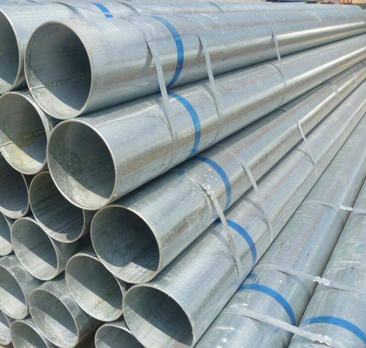
Black Steel Pipe and Galvanized Steel Pipe are both types of steel pipes used in various applications, and their main difference lies in their coating and resistance to rust and corrosion.
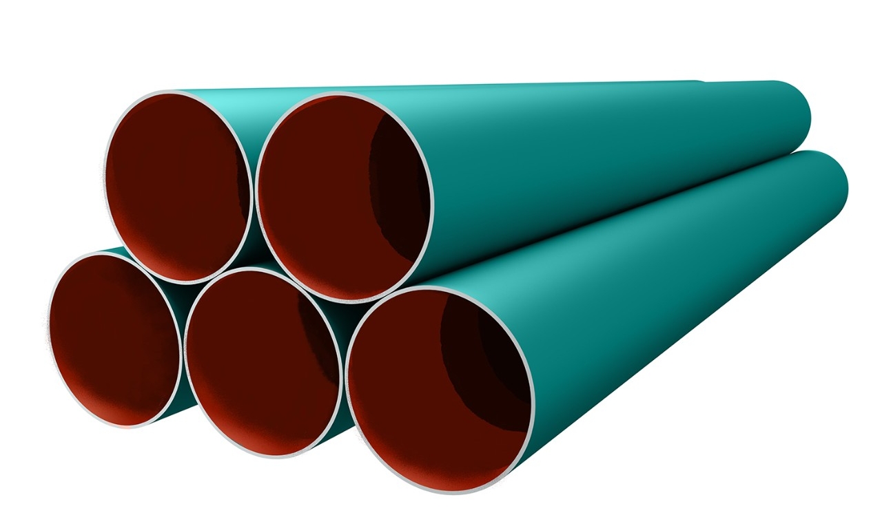
A hard, mechanically strong top coating for all fusion bonded epoxy pipeline corrosion protection coatings. It is applied to the base coating to form a tough outer layer that is resitant to gouge, impact, abrasion and penetration. abter steel is specifially designed to protect the primary corrosion coating from damage during pipeline directional drilling applications, bored, river crossing and installation in rough terrain.
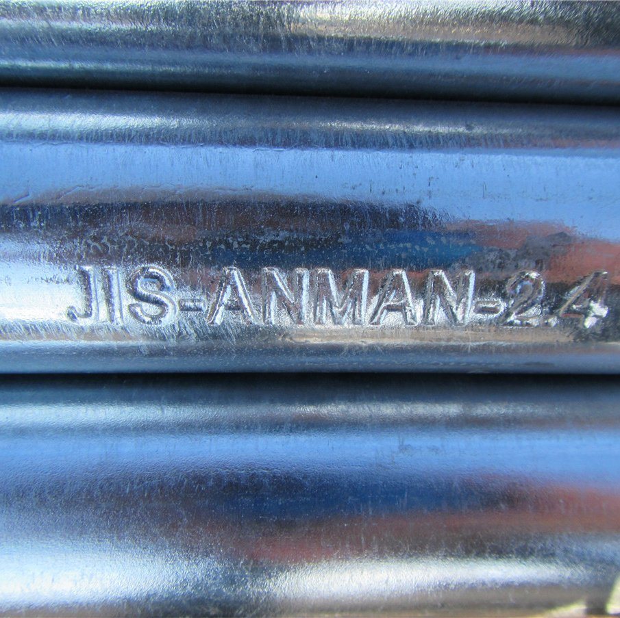
Brand new Chinese GB Japanese JIS American ASTM German DIN steel pipe standard comparison table
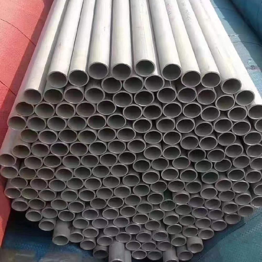
In industrial and residential applications, it is frequently necessary to join different types of metals. These connections can be between stainless steel and carbon steel, two of the most commonly used materials in piping systems. This article will walk you through the process of connecting stainless steel pipe to carbon steel pipe fittings, the challenges involved, and how to overcome them.
Based on the information provided, the ASME B 36.10 and B 36.19 standards define the dimensions and weight of welded and seamless steel pipes. These standards provide guidelines for the manufacturing and installation of steel pipes in various industries, including oil and gas, petrochemical, and power generation. ASME B 36.10 specifies the dimensions and weights of welded and seamless wrought steel pipes. It covers pipes ranging from NPS 1/8 (DN 6) through NPS 80 (DN 2000) and includes various wall thicknesses and schedules. The dimensions covered include outside diameter, wall thickness, and weight per unit length.
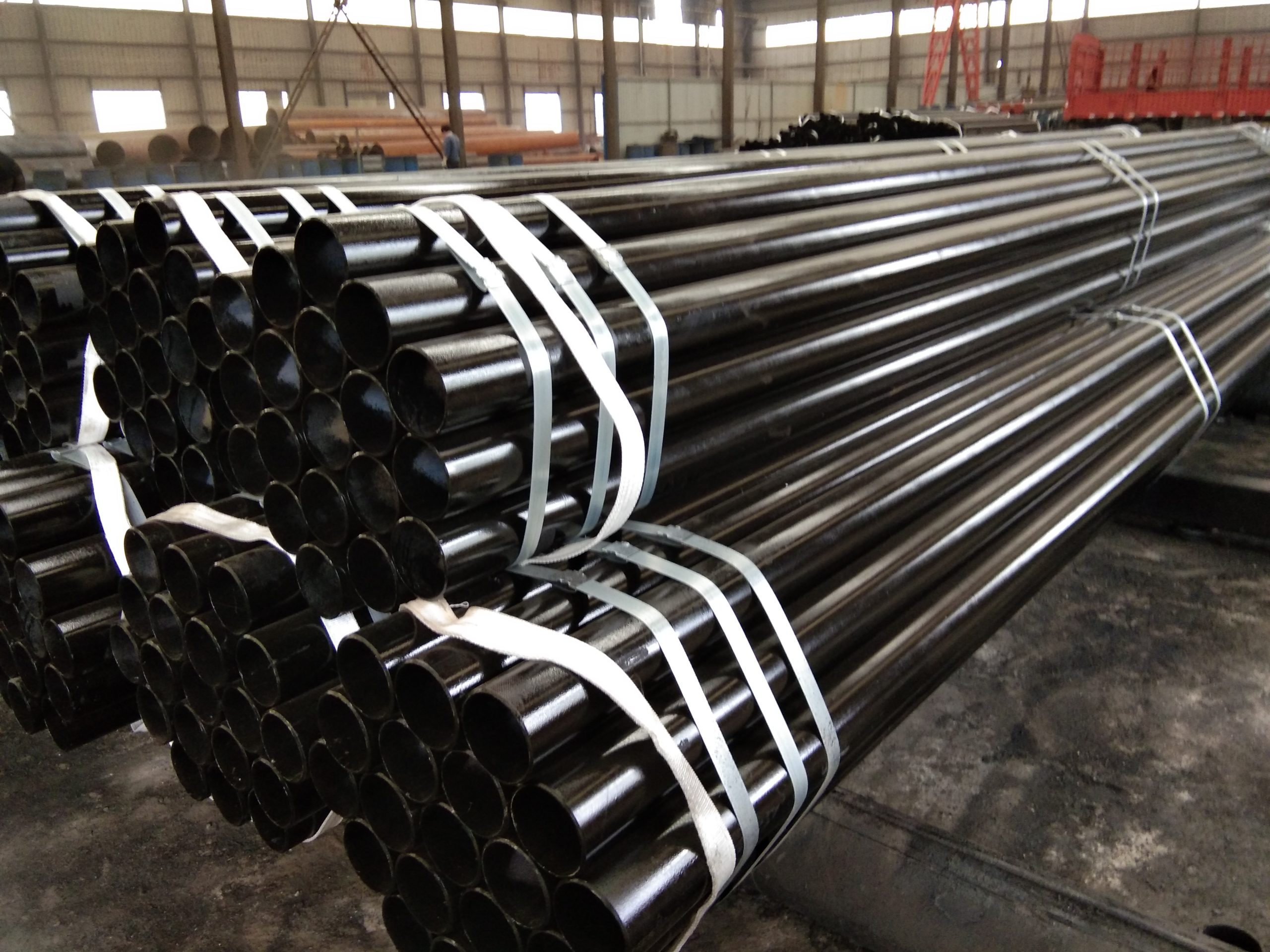
Carbon steel pipe and black steel pipe are often used interchangeably, but there are some key differences between the two. Composition: Carbon Steel Pipe is made up of carbon as the main alloying element, along with other elements such as manganese, silicon, and sometimes copper. This composition gives carbon steel pipe its strength and durability. On the other hand, black steel pipe is a type of carbon steel pipe that has not undergone any additional surface treatment or coating. Surface Finish: The most apparent difference between carbon steel pipe and black steel pipe is the surface finish. Carbon steel pipe has a dark, iron oxide coating called mill scale, which forms during the manufacturing process. This mill scale gives carbon steel pipe its black appearance. In contrast, black steel pipe has a plain, uncoated surface. Corrosion Resistance: Carbon steel pipe is susceptible to corrosion due to its iron content. However, the mill scale coating on carbon steel pipe provides some level of protection against corrosion, especially in indoor or dry environments. On the other hand, black steel pipe is more prone to corrosion since it lacks any protective coating. Therefore, black steel pipe is not recommended for use in areas exposed to moisture or corrosive elements.