A179 / SA179 HEAT EXCHANGER PIPE
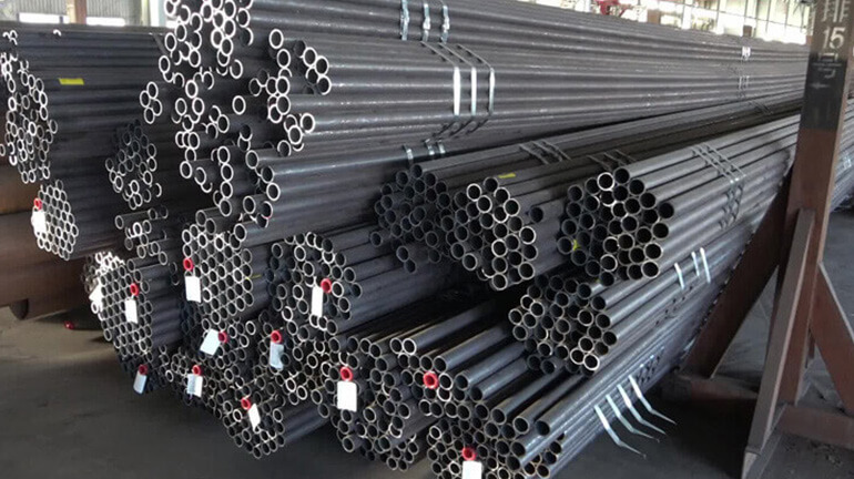
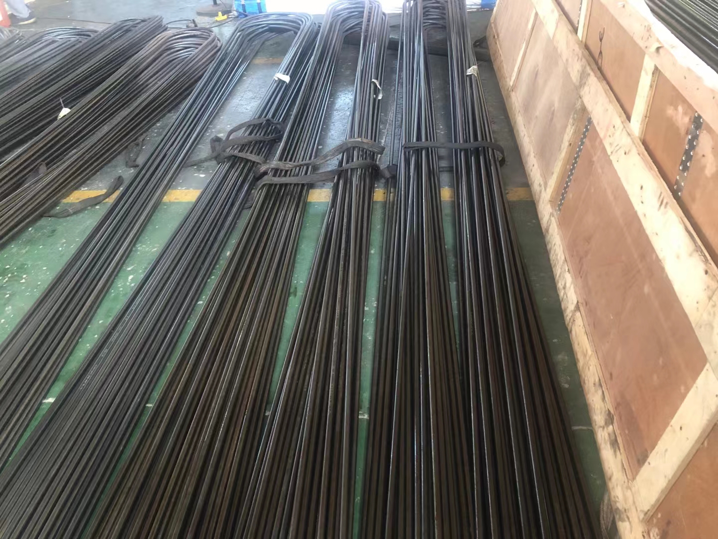
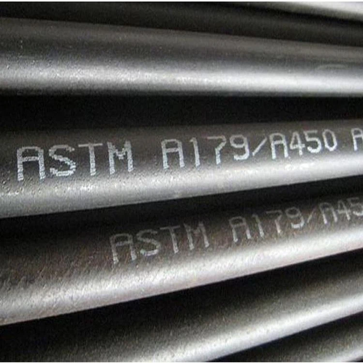
ASTM A179 (also known as ASME SA179) is a standard specification for seamless cold-drawn low-carbon steel heat exchanger and condenser tubes. These tubes are designed for use in heat exchangers, condensers, and other heat transfer applications where the operating temperature ranges from -20°F to 450°F (-29°C to 232°C). ASTM A179/ASME SA179 heat exchanger tubes are widely used in industries such as HVAC, power plants, petrochemical, and chemical processing.
Manufacture:Seamless process ,cold drawn.
Wall thickness(WT): 2.0 mm——12.7 mm.
Outer diameter (OD): 12.7mm——76.2 mm
Some key features of ASTM A179/ASME SA179 heat exchanger tubes include:
- Seamless construction: The tubes are cold-drawn and seamless, which ensures uniformity in wall thickness and enhanced mechanical properties.
- Low carbon content: The low-carbon steel used in these tubes provides good heat transfer properties and resistance to oxidation at high temperatures.
- Dimensional accuracy: The tubes are manufactured with strict dimensional tolerances, ensuring a proper fit in heat exchanger and condenser applications.
- Surface finish: The tubes have a smooth internal surface that reduces friction and promotes efficient heat transfer.
- Wide range of sizes: ASTM A179/ASME SA179 heat exchanger tubes are available in various outer diameters, wall thicknesses, and lengths to accommodate different heat transfer requirements.
Some common applications of ASTM A179/ASME SA179 heat exchanger tubes are:
- Heat exchangers in power plants
- Condensers in air conditioning systems
- Evaporator tubes in refrigeration systems
- Heat transfer equipment in chemical and petrochemical industries
To ensure the quality and performance of ASTM A179/ASME SA179 heat exchanger tubes, they undergo various tests, including hydrostatic testing, flattening testing, flaring testing, and non-destructive testing such as eddy current testing, ultrasonic testing, and radiographic testing. When selecting and installing these tubes in your project, it’s crucial to work with an engineer or a professional who can guide you on the right material selection, installation practices, and adherence to relevant safety standards and regulations.
ASTM A179,ASME SA179 Seamless Tube Specification:
| OD (mm) | Wall Thickness(mm) | |||||||||||||
| 2 | 2.5 | 3 | 3.5 | 4 | 4.5 | 5 | 6 | 6.5-7 | 7.5-8 | 8.5-9 | 9.5-10 | 11 | 12 | |
| Φ25-Φ28 | ● | ● | ● | ● | ● | ● | ||||||||
| Φ32 | ● | ● | ● | ● | ● | ● | ||||||||
| Φ34-Φ36 | ● | ● | ● | ● | ● | ● | ||||||||
| Φ38 | ● | ● | ● | ● | ● | ● | ||||||||
| Φ40 | ● | ● | ● | ● | ● | |||||||||
| Φ42 | ● | ● | ● | ● | ● | |||||||||
| Φ45 | ● | ● | ● | ● | ● | ● | ||||||||
| Φ48-Φ60 | ● | ● | ● | ● | ● | ● | ● | |||||||
| Φ63.5 | ● | ● | ● | ● | ● | ● | ● | |||||||
| Φ68-Φ73 | ● | ● | ● | ● | ● | ● | ||||||||
| Φ76 | ● | ● | ● | ● | ● | ● | ● | ● | ● | ● | ||||
Manufacture
ASTM A179,ASME SA179 steel tubes are made by the seamless process and shall be cold drawn.
Heat Treatment of ASTM A179,ASME SA179
ASTM A179,ASME SA179 steel tubes are heat treated after the final cold draw pass at a temperature of 1200°F [650°C] or higher.
Chemical Composition of ASTM A179,ASME SA179 Seamless Heat-Exchanger and Condenser Tubes
| Material | Chemical Composition(%) | ||||
| C | Si | Mn | P | S | |
| ASTM A179 | 0.06-0.18 | ≤ 0.25 | 0.27-0.63 | ≤0.035 | ≤0.035 |
Mechanical Propertie of ASTM A179,ASME SA179 Seamless Heat-Exchanger and Condenser Tubes
| Grade | ASTM A179 |
| Tensile Strength(MPa) | ≥325 |
| Yield Strength(MPa) | ≥180 |
| Elongation,% | ≥35 |
| Hardness, HRB | ≤72 |
Note —Tubing smaller in outside diameter and having a thinner wall than indicated in this specification is available. Mechanical property requirements do not apply to tubing smaller than 1/8 in. [3.2 mm] in outside diameter or with a wall thickness under 0.015 in. [0.4 mm].
The dimensional tolerances of ASTM A179,ASME SA179 Seamless Heat-Exchanger and Condenser Tubes
Tolerances of Wall Thickness
| Outside Diameter, in. [mm] |
Wall Thickness, % | |||||||
| 0.095[2.4] and Under | Over 0.095 to 0.150 [2.4 to 3.8], incl |
Over 0.150 to 0.180 [3.8 to 4.6], incl |
Over 0.180,[4.6] | |||||
| Over | Under | Over | Under | Over | Under | Over | Under | |
| Seamless, Cold-Finished Tubes | ||||||||
| Over | Under | |||||||
| 1 1 ⁄ 2 [38.1] and under | 20 | 0 | ||||||
| Over 1 1 ⁄ 2 [38.1] | 22 | 0 | ||||||
Tolerances of Outside Diameter
| Outside Diameter,in. [mm] | Permissible Variations, in. [mm] | |
| Over | Under | |
| Under 1 [25.4] | 0.004 [0.1] | 0.004 [0.1] |
| 1 to 1 1 ⁄ 2 [25.4 to 38.1], incl | 0.006 [0.15] | 0.006 [0.15] |
| Over 1 1 ⁄ 2 to 2 [38.1 to 50.8], excl | 0.008 [0.2] | 0.008 [0.2] |
| 2 to 2 1 ⁄ 2 [50.8 to 63.5], excl | 0.010 [0.25] | 0.010 [0.25] |
| 2 1 ⁄ 2 to 3 [63.5 to 76.2], excl | 0.012 [0.3] | 0.012 [0.3] |
| 3 to 4 [76.2 to 101.6], incl | 0.015 [0.38] | 0.015 [0.38] |
| Over 4 to 7 1 ⁄ 2 [101.6 to 190.5], incl | 0.015 [0.38] | 0.025 [0.64] |
| Over 7 1 ⁄ 2 to 9 [190.5 to 228.6], incl | 0.015 [0.38] | 0.045 [1.14] |
Tolerances of Length
| Method of Manufacture |
Outside Diameter, in. [mm] |
Cut Length,in. [mm] | |
| Over | Under | ||
| Seamless, cold-finished | Under 2 [50.8] | 1 ⁄ 8 [3] | 0 [0] |
| 2 [50.8] and over | 3 ⁄ 16 [5] | 0 [0] | |
| 2 [50.8] and over | 3 ⁄ 16 [5] | 0 [0] | |
U-Bend Fabrication Tolerances
| Item | Condition (when) | Tolercance |
|---|---|---|
| Nominal bend radius ≤ 2 x nominal OD | less than or equal to 12% | |
| Ovality | 2 x nominal OD < Nominal bend radius ≤ 4 x nominal OD | less than or equal to 10% |
| Nominal bend radius > 4 x nominal OD | less than or equal to 5% | |
| Nominal bend radius ≤ 2 x nominal OD | 0.75 x nominal wall | |
| Mimimum wall thickness | 2 x nominal OD < Nominal bend radius ≤ 4 x nominal OD | 0.8 x nominal wall |
| Nominal bend radius > 4 x nominal OD | 0.9 x nominal wall | |
| Nominal bend radius ≤ 8″ (200mm) | +/-3/64″(1mm) | |
| Bending Radius | 8″ (200mm) < Nominal bend radius ≤ 16″ (400mm) | +/-1/16″(1mm) |
| Nominal bend radius >16″ (400mm) | +/-5/64″(1mm) | |
| Disrance between legs | Max 1/16″(1.5mm) | |
| Wall thinning of bending area | Max 17% | |
| Difference between leg lengths at the ends | Leg length ≤ 16′ (4.88m) | +1/8″(3mm) |
| Leg length > 16′ (4.88m) | +3/16″(5mm) | |
| Deviation from plane of bend | ≤ 3/16″(1.5mm) | |
| Flattening on bend | ≤ 10% nominal diameter | |
| Straight leg length | ≤5m | +1/8″(3mm) |
| >5m | +3/16(5mm) | |
| Total tube length including radius | ≤6m | +3/16(5mm) |
| >6m | +5/16″(8mm) |
SA-450/SA-450M
| OD In (mm) | + | – | WT In (mm) | + | – |
|---|---|---|---|---|---|
| <1(25.4) | 0.10 | 0.10 | ≤1.1/2(38.1) | 20% | 0 |
| 1∼1.1/2(25.4∼38.1) | 0.15 | 0.15 | >1.1/2(38.1) | 22% | 0 |
| >1.1/2∼<2(38.1∼50.8) | 0.20 | 0.20 | |||
| 2∼<2.1/2(50.8∼63.5) | 0.25 | 0.25 | |||
| 2.1/2∼<3(63.5∼76.2) | 0.30 | 0.30 | |||
| 3∼4(76.2∼101.6) | 0.38 | 0.38 | |||
| >4∼7.1/2(101.6∼190.5) | 0.38 | 0.64 | |||
| >7.1/2∼9(190.5∼228.6) | 0.38 | 1.14 |
Pressure Temperature Rating
| NPS (in) |
Outside Diameter (in) |
ASTM A106 Grade B Pipe Schedule | ||||||||||||
|---|---|---|---|---|---|---|---|---|---|---|---|---|---|---|
| SCH 10 | SCH 20 | SCH 30 | SCH STD | SCH 40 | SCH 60 | SCH XS | SCH 80 | SCH 100 | SCH 120 | SCH 140 | SCH 160 | SCH XXS | ||
| Wall Thickness (in) | ||||||||||||||
| 1/8 | 0.405 | 0.068 | 0.068 | 0.095 | 0.095 | |||||||||
| 1/4 | 0.540 | 0.088 | 0.088 | 0.119 | 0.119 | |||||||||
| 3/8 | 0.675 | 0.091 | 0.091 | 0.126 | 0.126 | |||||||||
| 1/2 | 0.840 | 0.109 | 0.109 | 0.147 | 0.147 | 0.187 | 0.294 | |||||||
| 3/4 | 1.050 | 0.113 | 0.113 | 0.154 | 0.154 | 0.219 | 0.308 | |||||||
| 1 | 1.315 | 0.133 | 0.133 | 0.179 | 0.179 | 0.250 | 0.358 | |||||||
| 1 1/4 | 1.660 | 0.140 | 0.140 | 0.191 | 0.191 | 0.250 | 0.382 | |||||||
| 1 1/2 | 1.900 | 0.145 | 0.145 | 0.200 | 0.200 | 0.281 | 0.400 | |||||||
| 2 | 2.375 | 0.154 | 0.154 | 0.218 | 0.218 | 0.344 | 0.436 | |||||||
| 2 1/2 | 2.875 | 0.203 | 0.203 | 0.276 | 0.276 | 0.375 | 0.552 | |||||||
| 3 | 3.500 | 0.216 | 0.216 | 0.300 | 0.300 | 0.438 | 0.600 | |||||||
| 3 1/2 | 4.000 | 0.226 | 0.226 | 0.318 | 0.318 | |||||||||
| 4 | 4.500 | 0.237 | 0.237 | 0.337 | 0.337 | 0.438 | 0.531 | 0.674 | ||||||
| 5 | 5.563 | 0.258 | 0.258 | 0.375 | 0.375 | 0.500 | 0.625 | 0.750 | ||||||
| 6 | 6.625 | 0.280 | 0.280 | 0.432 | 0.432 | 0.562 | 0.719 | 0.864 | ||||||
| 8 | 8.625 | 0.250 | 0.277 | 0.322 | 0.322 | 0.406 | 0.500 | 0.500 | 0.594 | 0.719 | 0.812 | 0.906 | 0.875 | |
| 10 | 10.750 | 0.250 | 0.307 | 0.365 | 0.365 | 0.500 | 0.500 | 0.594 | 0.719 | 0.844 | 1.000 | 1.125 | 1.000 | |
| 12 | 12.750 | 0.250 | 0.330 | 0.375 | 0.406 | 0.562 | 0.500 | 0.688 | 0.844 | 1.000 | 1.125 | 1.312 | 1.000 | |
| 14 | 14.000 | 0.250 | 0.312 | 0.375 | 0.375 | 0.438 | 0.594 | 0.500 | 0.750 | 0.938 | 1.094 | 1.250 | 1.406 | |
| 16 | 16.000 | 0.250 | 0.312 | 0.375 | 0.375 | 0.500 | 0.656 | 0.500 | 0.844 | 1.031 | 1.219 | 1.438 | 1.594 | |
| 18 | 18.000 | 0.250 | 0.312 | 0.438 | 0.375 | 0.562 | 0.750 | 0.500 | 0.938 | 1.156 | 1.375 | 1.562 | 1.781 | |
| 20 | 20.000 | 0.250 | 0.375 | 0.500 | 0.375 | 0.594 | 0.812 | 0.500 | 1.031 | 1.281 | 1.500 | 1.750 | 1.969 | |
| 22 | 22.000 | 0.250 | 0.375 | 0.500 | 0.375 | 0.875 | 0.500 | 1.125 | 1.375 | 1.625 | 1.875 | 2.125 | ||
| 24 | 24.000 | 0.250 | 0.375 | 0.562 | 0.375 | 0.688 | 0.969 | 0.500 | 1.219 | 1.531 | 1.812 | 2.062 | 2.344 | |
| 30 | 30.000 | 0.312 | 0.500 | 0.625 | 0.375 | 0.500 | ||||||||
| 32 | 32.000 | 0.312 | 0.500 | 0.625 | 0.375 | 0.688 | ||||||||
| 34 | 34.000 | 0.312 | 0.500 | 0.625 | 0.375 | 0.688 | ||||||||
| 36 | 36.000 | 0.312 | 0.500 | 0.625 | 0.375 | 0.750 | ||||||||
| 42 | 42.000 | 0.500 | 0.625 | 0.375 | 0.750 | |||||||||
What are the advantages of using ASTM A179/ASME SA179 heat exchanger tubes over other materials?
ASTM A179/ASME SA179 heat exchanger tubes offer several advantages over other materials in heat exchanger and condenser applications. Some of these benefits include:
Excellent heat transfer properties: The low-carbon steel used in ASTM A179/ASME SA179 tubes has good thermal conductivity, which allows for efficient heat transfer between the fluid inside the tube and the surrounding environment.
High corrosion resistance: The low-carbon steel composition of these tubes provides resistance to oxidation and corrosion at high temperatures, making them suitable for various industrial applications where corrosive environments are common.
Seamless construction: ASTM A179/ASME SA179 tubes are cold-drawn and seamless, ensuring uniform wall thickness and improved mechanical properties. This seamless construction reduces the risk of leaks and enhances the tube’s overall strength and durability.
Dimensional accuracy: These tubes are manufactured with strict dimensional tolerances, ensuring a proper fit in heat exchanger and condenser applications. This accuracy helps prevent leakage and ensures efficient heat transfer.
Cost-effective: Low-carbon steel, such as that used in ASTM A179/ASME SA179 tubes, is generally more cost-effective than other materials like stainless steel or high-alloy steels. This makes them an attractive option for projects with budget constraints.
Ease of fabrication: The low-carbon steel used in these tubes is relatively easy to work with, allowing for convenient fabrication processes like bending, welding, and flaring without compromising the material’s properties.
Wide range of sizes: ASTM A179/ASME SA179 heat exchanger tubes are available in various outer diameters, wall thicknesses, and lengths, making them suitable for a wide range of applications and accommodating different heat transfer requirements.
Despite these advantages, it is essential to consult with an engineer or a professional when selecting the appropriate material for your heat exchanger or condenser application. Factors such as operating temperature, pressure, corrosive environment, and specific industry standards should be taken into account when choosing the right material.

